Jvc KY-F550 User Manual
Browse online or download User Manual for Cameras Jvc KY-F550. JVC KY-F550 User Manual
- Page / 52
- Table of contents
- BOOKMARKS
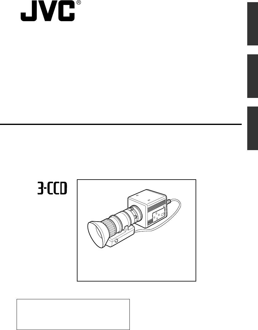
- COLOUR VIDEO CAMERA 1
- FARBVIDEOKAMERA 1
- APPAREIL VIDEO EN COULEURS 1
- SAFETY PRECAUTIONS 2
- JVC Sales Office 3
- Contents 4
- 1. Getting Started 6
- Points to Note During Use 7
- 1 Lens Mount 8
- 2 Camera Mounting Bracket 8
- 3 Fastening Screws for Camera 8
- Part Names and Functions 8
- 5 [MENU] Menu Button 9
- 6 [SET] Set Button 9
- 9 Function Setting Switch 10
- Description of Terminals 12
- PIN, Female) 13
- Digital Output Terminal 13
- AC ADAPTER AA-P700 14
- Mounting the Lens 17
- Connecting the Power Supply 18
- Mounting the Camera 19
- 12345 678 21
- White Balance Adjustment 22
- Error Display 23
- White Shading Adjustment 24
- 4. Various Modes of Shooting 26
- Output of Negative Image 27
- White Spot Correction 28
- Flow of Menu Screens 30
- BACKPAGE 31
- Setting Procedures 32
- “EXPOSURE” Screen 33
- “EXPOSURE” Screen (continued) 34
- “ADVANCED EXPOSURE” Screen 35
- “WHITE BALANCE” Screen 36
- “PROCESS (1/2)” Screen 38
- “KNEE” Function 39
- “PROCESS (2/2)” Screen 40
- “SYSTEM” Screen 41
- “MATRIX ADJUST” Screen 42
- “CAPTURE” Screen 43
- “FILE MANAGE” Screen 44
- Retrieve file 45
- Reset the set value 45
- 6. Others 46
- 6. Others (continued) 48
- Technical Information 49
- Specifications (continued) 51
Summary of Contents
KY-F550KY-F550 COLOUR VIDEO CAMERAINSTRUCTION MANUALBEDIENUNGSANLEITUNGMODE D’EMPLOI*Illustration with optional lens attachment.*Illustration mit mon
E-105 / BARS∞/ AWSETMENU12349ONOFF12349 Function Setting SwitchUse for setting the functions of this unit.Select the switches when the unit is at powe
E-11EnglishLENSDVVIDEO OUTTRGGERREMORTPOWERRGB, Y/C, SYNC OUTDC INSEE INSTRUCTION MANUAL10121113141516170[RGB, Y/C, SYNC OUT] AnalogueOutput TerminalO
E-121436785213564214367852142531. Getting Started (continued)Description of TerminalsPower Input Terminal (Mini DIN 8 Pin,Female)Pin No.12345678Remote
E-13English2461351569Description of Terminals (continued)Analogue Output Terminal (D-sub 9PIN, Female)Digital Output TerminalNotes● Cannot be connecte
E-14AC ADAPTER AA-P700ONOFFPOWER5 / BARS5 / AWSETMENU1234LENSDVVIDEO OUTTRGGERREMORTPOWERRGB, Y/C, SYNC OUTDC INSEE INSTRUCTION MANUALONOFF1234Compute
E-15EnglishConnecting Through Digital Output (continued)䡵 Specification of Compatible Computer● Pentium 4 2.4 GHz or higher DOS/V, PC/AT compatible ma
E-16ONOFF12342. Preparation Before Shooting (continued)MicroscopeAdapterConnecting Through Analogue OutputCaution● Perform this when the devices are o
E-17EnglishMounting the LensFollow the procedures below when mounting the auto iris lens.Refer to the ‘instruction manual’ for the lens as well.Cautio
E-18DC INPOWERVIDEO OUTPUTTO CAMERAS(Y/C) OUTPUTDC 12V=OUTPUTEITHEROUTPUTMAX 1.25ASEE INST-RUCTIONMANUALLENSDVVIDEO OUTTRGGERREMORTPOWERRGB, Y/C, SYNC
E-19EnglishMounting the Camera● To mount this unit, make use of the screw holesfor mounting the camera on the camera mountingbracket.● When mounting t
FrançaisPort Cable LengthVIDEO OUT Exclusive Cable 5 metersRGB,Y/C,SYNC OUT Exclusive Cable 2 metersLENS Exclusive Cable 0.4 metersTRIGGER Exclusive C
E-20Precautions to Prevent Camera From Falling● Special attention is required when mounting to the wall or ceiling. Get a contractorto perform the wor
E-21EnglishLENSDVVIDEO OUTTRGGERREMORTPOWERRGB, Y/C, SYNC OUTDC INSEE INSTRUCTION MANUAL5 / BARS∞/ AWSETMENU12343. Setting and Adjustment During Shoot
E-22WH IAUTO E1TRATOPE IONWHAUTO TIE1OK (3200K)-- ---CE-WHI TE BALANCEBALANTPRESEWH I T E0AUTO10LEVEL (R)LEVEL (B)LEVEL (R)LEVEL (G)LEVEL (B)SHADINGPA
E-23EnglishG:OBNJ E CT O WH AUT ITE 1 R:LOERRO W L I T GHO WH AUT ITE 1 R:OVERROE R L HT IGO WH AUT ITE 1 White Balance Ad
E-245 / BARS∞/ AWSETMENU1234--- MENU ---EXPOSURE . .WH I T E B ALANCE . .FILE M..PROCESS . .CAPTURE . .SYSTEM . .EX I TANAGE-- ---CE-WHI TE BALANCEBAL
E-25EnglishG:OBNJ E CTO SHADING AUTR:LOERRO W L I TGHO SHADINGAUTR: OVERERRO L H TIGO SHADINGAUTOPERATIONO SHADING AUTOKO SHADING AUT6.Press the
E-26--- ---EXPOSUREIRIS MODE AUTOSTEPSTEP0dBMA LAUNNO LAMRLEVELGA I N ELEV LSHUTTERLEVELADVANCEDEXPOSURE..BACKPAGE - - - - - ---- ---EXPOSUREIRIS MOD
E-27English5 / BARS∞/ AWSETMENU1234--- ---SYSTEMNEGA OF FTIVECANCELPENIPPAGEBACKDV SYSTEM JVCXEL COM--- ---SYSTEMNEGA ONTIVECANCEL
E-285 / BARS∞/ AWSETMENU12344. Various Modes of Shooting (continued)[MENU] [SET][5][∞]White Spot CorrectionAs a peculiar common characteristic of CCD,
E-29EnglishCOMPECUEXE TI NGNPIXELCOMPEERROR : LENS NOT CLOSED?NPIXELCOMPEERROR : LENS NOT CLOSED?NPIXELCOMPEOKNTURN POWER OFF AND ON AGAIN.P
E-3EnglishSAFETY PRECAUTIONS1. JVC Professional Europe Ltd.Ullswater House, Kendal Avenue,London W3 0XA U.K.tel: +44(020)8896-60002. JVC Professional
E-30--- MENU ---EXPOSURE . .WH I T E B ALANCE . .FILE M..PROCESS . .CAPTURE . .SYSTEM . .EX I TANAGE---ALC L IMITEE I MILITAE ELEV LAEAAREAE DETECADVA
E-31English--- ---ALC L IMIT+18dB0EE I MILNO LAMRITAE ELEV LAEAAREAE DETECADVANCEDTEXPOSURE..BACKPAGE 201/ 0--- ---RGAIN 0RR TATOIONMATR I XADJUSTBAC
E-325/ BARS∞/ AWSETMENU1234--- MENU ---EXPOSURE . .WH I T E B ALANCE . .FILE M..PROCESS . .CAPTURE . .SYSTEM . .EX I TANAGEONOFF1234--- ---EXPOSUREIRI
E-33EnglishItem“IRIS MODE”“MANUALLEVEL”“GAIN”“LEVEL”“SHUTTER”“EXPOSURE” ScreenFunction/Variable ValuesSwitch according to the lens in use.“AUTO” : Whe
E-34Item“SHUTTER”“LEVEL”“ADVANCEDEXPOSURE”“PAGE BACK”Function/Variable Values“EEI” : Adjusts shutter speed automatically according to brightnessof obj
E-35EnglishNoteThe “AE LEVEL”, “AE DETECT” and “AE AREA” items cannot be selected when operation of auto iris, “ALC”and “EEI” are set as disabled.The
E-36Function/Variable ValuesFor setting the white balance mode.“AUTO 1” : Set to this to enable automatic adjustment of white balance.“AUTO 2” : Equip
E-37EnglishItem“SHADING”“LEVEL (R)”“LEVEL (G)”“LEVEL (B)”“PAGE BACK”“WHITE BALANCE” Screen (continued)Function/Variable ValuesFor setting whether to p
E-38Item“MASTERBLACK”“DETAIL”“LEVEL”“V/H BALANCE”“FREQUENCY”“V. RESOLUTION”5. Setting Via the Menu Screen (continued)“PROCESS (1/2)” ScreenFunction/Va
E-39EnglishFunction/Variable ValuesFor setting a white clipping point for video signals of a high luminance level.“108%” : Enable white clipping at po
E-4Contents1. Getting StartedFeatures ...
E-40Function/Variable ValuesFor setting colour matrix.“OFF” : Disabled.“STANDARD” : Sets to standard colour matrix.“MANUAL” : Sets colour matrix to th
E-41EnglishItem“FLARE (R)”“FLARE (B)”“PAGE BACK”Function/Variable ValuesFor correcting Rch of black level in accordance with the luminance level whenl
E-425. Setting Via the Menu Screen (continued)“MATRIX ADJUST” ScreenSettings in bold are factory settingsItem“R GAIN”“R ROTATION”“G GAIN”“G ROTATION”“
E-43EnglishFunction/Variable ValuesFor capturing images into the memory and output still images (frozen images) throughthe various output terminals lo
E-44--- MENU ---EXPOSURE . .WH I T E B ALANCE. .PROCESS . ...SYSTEM . .FILE M..CAPTUREEX I TANAGE--- ---LOAD F I LE ALOADFILE MANAGEBACKPAGE CANCELST
E-45English--- ---LOAD F I LE ALOADFILE MANAGEBACKPAGE CANCELSTOREEFILE ASTORCANCELRESETTFILE ARESECANCEL--- ---LOAD F I LE ALOADFILE MANAGEBACKPAGE
E-46Connecting the Remote Control Unit6. OthersMenu function of the camera can be set using the remote control unit (RM-LP55 AND RM-LP57). (Pleaserefe
E-47EnglishConnecting the Remote Control Unit (continued) List of Remote Control Unit FunctionsO ... Function availablex ... Function not available1.
E-486. Others (continued)ONOFF1234● Attach the supplied clamp filter as shown in thediagram on the left to reduce unwanted electro-magnetic emission.●
EnglishE-49EnglishTechnical InformationWEN output signalImage output signalAccumulated CCDcharges● SLOW SHUT 3 FRM SettingSI output signalImage output
EnglishE-5English5. Setting Via the Menu ScreenFlow of Menu Screens ...
E-50Specifications6. Others (continued)Image Pickup Device : 1/3" IT CCD x 3Scan Mode : InterlaceEffective Pixel Numbers : 440,000 Pixels (752 (H
E-51EnglishWILL RESULT.LENSSC45550-011PROTRUDES MORE THANATTACH A LENS WHICHNEVERMAX4mm4mm SEVERE DAMAGEWARNING:BARSMENUSET1234AW8093.60.56667.564Dime
E-52...
E-6Features1. Getting Started● High quality images can be obtained through high sensitivity of 2000 lx (F11) and high resolution ofhorizontal resoluti
E-7EnglishPoints to Note During Use● For important shootings, perform trials in advance to ensure that they are properly recorded.● We will not compen
E-841231 Lens MountFor mounting lens. Suitable for C mount lensmeant for 3 CCDs.☞ Page 17 ‘Mounting the Lens’2 Camera Mounting BracketSupplied togethe
E-9English5 / BARS∞ / AWSETMENU12345 7 685 [MENU] Menu ButtonPress this button for 1-2 seconds. Menu screenwill be output from the various output term
Related products and manuals for Cameras Jvc KY-F550
 (7 pages)
(68 pages)
(88 pages)
(7 pages)
(68 pages)
(88 pages)

 (96 pages)
(92 pages)
(112 pages)
(96 pages)
(92 pages)
(112 pages)
 (148 pages)
(56 pages)
(52 pages)
(44 pages)
(56 pages)
(56 pages)
(88 pages)
(90 pages)
(44 pages)
(30 pages)
(52 pages)
(52 pages)
(148 pages)
(56 pages)
(52 pages)
(44 pages)
(56 pages)
(56 pages)
(88 pages)
(90 pages)
(44 pages)
(30 pages)
(52 pages)
(52 pages)
© 2020, manymanuals.com. All rights reserved. | 2.119 s |
 Manymanuals.com
 Manymanuals.de
 Manymanuals.fr
 Manymanuals.it
 Manymanuals.pl
 Manymanuals.cz
 Manymanuals.es
 Manymanuals-pt.com
Comments to this Manuals