Jvc KD-R901 User Manual

Browse online or download User Manual for Car radio Jvc KD-R901. JVC KD-R901 Manuel d'utilisation

  • Download
  • Add to my manuals
  • Print
  • Page
    / 6
  • Table of contents
  • BOOKMARKS
  • Rated. / 5. Based on customer reviews
Page view 0
1
KD-R901
Installation/Connection Manual
Manuel d’installation/raccordement
GET0610-010A
[EX/EU]
J
Handles
Poignées
I
Rubber cushion
Amortisseur en caoutchouc
A / B
Hard case/Control panel
Etui de transport/Panneau
de commande
C
Sleeve
Manchon
D
Trim plate
Plaque d’assemblage
ENGLISH
This unit is designed to operate on 12 V DC, NEGATIVE ground electrical systems. If your vehicle
does not have this system, a voltage inverter is required, which can be purchased at JVC IN-CAR
ENTERTAINMENT dealers.
Parts list for installation and connection
The following parts are provided for this unit. If any item is missing, consult your JVC IN-CAR
ENTERTAINMENT dealer immediately.
N
Remote controller
Télécommande
O
Battery
Pile
FRANÇAIS
Cet appareil est conçu pour fonctionner sur des sources de courant continu de 12 V à masse NEGATIVE.
Si votre véhicule n’offre pas ce type d’alimentation, il vous faut un convertisseur de tension, que vous pouvez
acheter chez un revendeur d’autoradios JVC.
Liste des pièces pour l’installation et raccordement
Les pièces suivantes sont fournies avec cet appareil. Si quelque chose manquait, consultez votre revendeur
autoradio JVC immédiatement.
0209DTSMDTJEIN
EN, FR
© 2009 Victor Company of Japan, Limited
WARNINGS
To prevent short circuits, we recommend that you disconnect the battery’s negative terminal and make all
electrical connections before installing the unit.
Be sure to ground this unit to the car’s chassis again after installation.
Notes:
Replace the fuse with one of the specified rating. If the fuse blows frequently, consult your JVC IN-CAR
ENTERTAINMENT dealer.
It is recommended to connect speakers with a maximum power of more than 50 W (both at the
rear and at the front, with an impedance of 4 Ω to 8 Ω). If the maximum power is less than 50 W,
change <Amplifier Gain> setting to prevent the speakers from being damaged (see page 29 of the
INSTRUCTIONS).
To prevent short circuits, cover the terminals of the UNUSED leads with insulating tape.
The heat sink becomes very hot after use. Be careful not to touch it when removing this unit.
Heat sink / Dissipateur de chaleur
AVERTISSEMENTS
Pour éviter tout court-circuit, nous vous recommandons de débrancher la borne négative de la batterie et
d’effectuer tous les raccordements électriques avant d’installer l’appareil.
Assurez-vous de raccorder de nouveau la mise à la masse de cet appareil au châssis de la
voiture après l’installation.
Remarques:
Remplacer le fusible par un de la valeur précisée. Si le fusible saute souvent, consulter votre revendeur
d’autoradios JVC.
Il est recommandé de connecter des enceintes avec une puissance maximum de plus de 50 W (à
l’arrière et à l’avant et avec une impédance de 4 Ω à 8 Ω). Si la puissance maximum est inférieure à
50 W, changez <Amplifier Gain> pour éviter d’endommager vos enceintes (voir page 29 du MANUEL
D’INSTRUCTIONS).
Pour éviter les courts-circuits, recouvrez les extrémités des fils INUTILISÉS avec une bande isolante.
Le dissipateur de chaleur devient très chaud après usage. Faire attention de ne pas le toucher en retirant
cet appareil.
K
USB Bluetooth adapter
Adaptateur USB Bluetooth
L
Microphone
Microphone
M
Microphone clips
Attaches de microphone
PRECAUTIONS on power supply and speaker connections:
DO NOT connect the speaker leads of the power cord to the car battery; otherwise, the unit
will be seriously damaged.
BEFORE connecting the speaker leads of the power cord to the speakers, check the speaker wiring in
your car.
PRECAUTIONS sur l’alimentation et la connexion des enceintes:
NE CONNECTEZ PAS les fils d’enceintes du cordon d’alimentation à la batterie; sinon,
l’appareil serait sérieusement endommagé.
AVANT de connecter les fils d’enceintes du cordon d’alimentation aux enceintes, vérifiez le câblage des
enceintes de votre voiture.
F
Washer (ø5)
Rondelle (ø5)
G
Lock nut (M5)
Ecrou d’arrêt (M5)
H
Mounting bolt (M4 × 5 mm; M5 × 12.5 mm)
Boulon de montage (M4 × 5 mm; M5 × 12,5 mm)
E
Power cord
Cordon d’alimentation
Install1_KD-R901_010A_3.indd 1Install1_KD-R901_010A_3.indd 1 19/2/09 2:56:57 PM19/2/09 2:56:57 PM
Page view 0
1 2 3 4 5 6

Summary of Contents

Page 1 - AVERTISSEMENTS

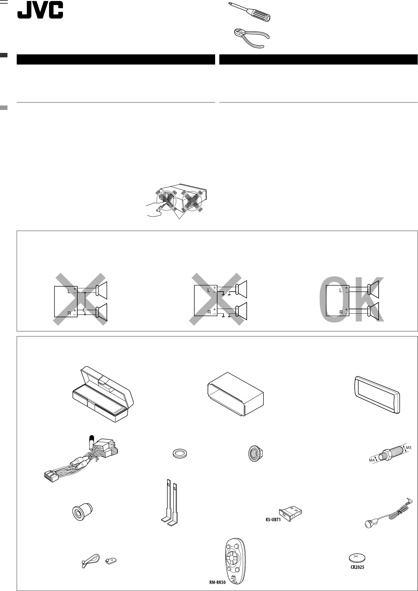
1KD-R901Installation/Connection ManualManuel d’installation/raccordementGET0610-010A[EX/EU]JHandlesPoignéesIRubber cushionAmortisseur en caoutchoucA /

Page 2

2When using the optional stay / Lors de l’utilisation du hauban en optionBracket*3Support*3PocketPocheFlat head screws (M5 × 8 mm)*3Vis à tête plate (

Page 3 - RACCORDEMENTS ELECTRIQUES

3BLINE OUT(see diagram / voir le diagramme )Rear ground terminal / Borne arrière de masse15 A fuse / Fusible 15 AAerial terminalBorne de l’antenneBl

Page 4 - ENGLISH FRANÇAIS

4 ENGLISH FRANÇAISC Connecting the external amplifiers and subwoofer / Connexion d’amplificateurs extérieurs et d’un caisson de graveRemote lead (b

Page 5

5 Connecting the microphone unit / Connexion du microphoneAdjust the microphone angleAjustez l’angle du microphoneMicrophoneMicrophoneMicrophone clip

Page 6 - CAUTION:

6Lors de la connexion des appareils extérieurs, référez-vous aussi aux manuels fournis avec les appareils et les adaptateurs.PRECAUTION: Avant de con

Comments to this Manuals

No comments